Shadow outlines tutorial
In one of my showcases I recreated a piece of art by Malin, which involves these warm shadow outlines that I really liked. There are however few sources or tutorials on how to achieve this, so I made this “beginner” friendly tutorial on how to get shadow outlines in Unity 2020.3 URP with a written HLSL shader.
In this tutorial I will show you how to sample the shadow map of the main light, make a Lambert based toon lighting model and draw outlines around the shadows.
This tutorial was made with Unity 2020.3.1f1 and the Universal Render Pipeline (URP). Note that the general concept can be applied to any shader environment. You can get the project files here, including the initial and finished shader.
Acknowledgements
This tutorial is based on my Art recreation (Malin) post, and thus I’d first like to acknowledge Malin for the beautiful art piece that set me on this path. On a more technical note, the following tutorials/breakdowns/articles were used directly or useful for the making of this tutorial:
- This tweet on shadow outlines in Unity’s built-in render pipeline, by Shahriar Shahrabi
- This video on edge detection, by NedMakesGames
- This article on edge detection, by Alex Ameye
Contents
1 Basic setup
If you’re using the project files you can simply open “InitialScene.scene” and “ShadowOutlines.shader” and skip to section 1.2.
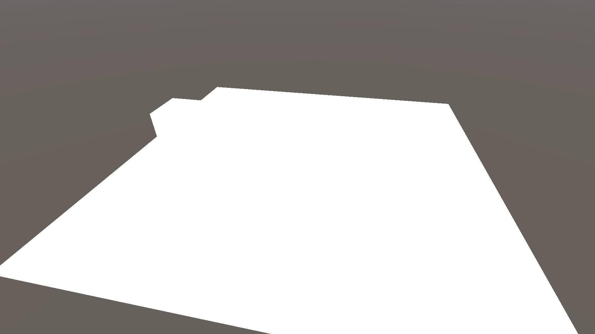
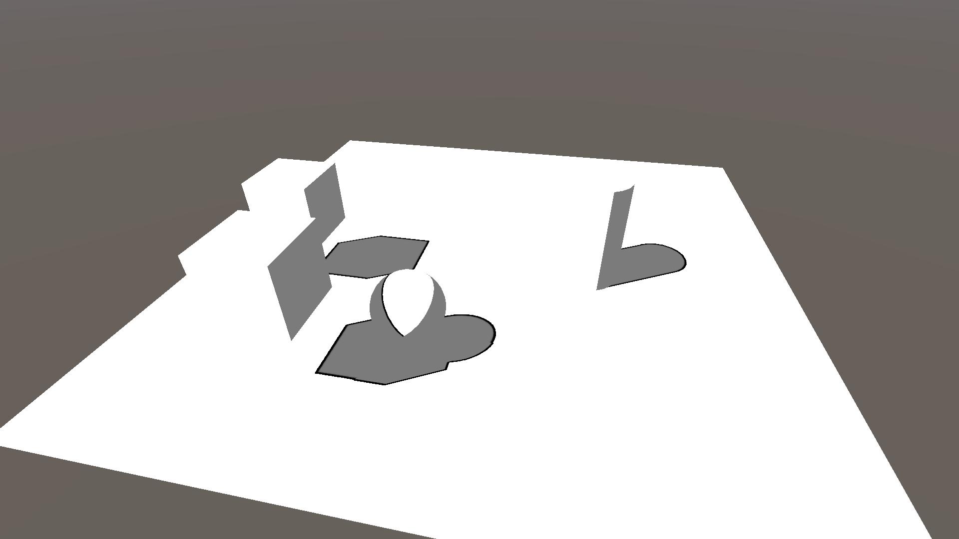
We start by creating a new scene consisting of a plane and some primitive shapes (cube, sphere & cylinder). As well as a new unlit shader ShadowOutlines.shader and its material, which we’ll apply to all objects in the scene. All objects in the scene should be white now, with no shadows what so ever.
1.1 HLSL shader
The standard unlit shader we made is a CGPROGRAM, but we’ll be using URP’s HLSL library files so we’ll rewrite the shader as a HLSLPROGRAM. Replace all lines in ShadowOutlines.shader with the following code block.
This shader contains two passes, the ForwardLit pass and the ShadowCaster pass. The ForwardLit pass only calculates the vertex position and normal in world space and outputs a white colour. The ShadowCaster pass renders our object to the shadow map. Note that we don’t see any shadows yet, this is because we are not sampling the shadow map in the ForwardLit pass.
For the rest of the tutorial you can ignore the ShadowCaster pass, as the shadows and outlines are calculated and applied in the ForwardLit pass.
Shader "KelvinvanHoorn/ShadowOutlines"
{
    Properties
    {
    }
    SubShader
    {
        Tags { "RenderType"="Opaque" "RenderPipeline" = "UniversalRenderPipeline"}
        Cull Back

        Pass
        {
            Name "ForwardLit"
            Tags { "LightMode" = "UniversalForward" }

            HLSLPROGRAM
            #pragma vertex vert
            #pragma fragment frag

            #include "Packages/com.unity.render-pipelines.universal/ShaderLibrary/Core.hlsl"

            struct Attributes
            {
                float4 vertex   : POSITION;
                float3 normal   : NORMAL;
            };

            struct Varyings
            {
                float4 posCS        : SV_POSITION;
                float3 posWS        : TEXCOORD0;
                float3 normalWS     : TEXCOORD1;
            };

            Varyings vert(Attributes IN)
            {
                Varyings OUT = (Varyings)0;;
                VertexPositionInputs vertexInput = GetVertexPositionInputs(IN.vertex.xyz);
                OUT.posCS = vertexInput.positionCS;
                OUT.posWS = vertexInput.positionWS;

                VertexNormalInputs normalInput = GetVertexNormalInputs(IN.normal);
                OUT.normalWS = normalInput.normalWS;

                return OUT;
            }

            float4 frag (Varyings IN) : SV_Target
            {
                float3 col = float3(1, 1, 1);

                return float4(col, 1);
            }
            ENDHLSL
        }
        pass
        {
            Name "ShadowCaster"
            Tags{"LightMode" = "ShadowCaster"}

            ZWrite On
            ZTest LEqual
            ColorMask 0

            HLSLPROGRAM

            #include "Packages/com.unity.render-pipelines.universal/ShaderLibrary/Core.hlsl"
            #include "Packages/com.unity.render-pipelines.universal/ShaderLibrary/Lighting.hlsl"

            #pragma vertex vert
            #pragma fragment frag

            struct Attributes
            {
                float4 vertex   : POSITION;
                float3 normal   : NORMAL;
            };

            struct Varyings
            {
                float4 posCS        : SV_POSITION;
            };

            float3 _LightDirection;

            Varyings vert(Attributes IN)
            {
                    Varyings OUT = (Varyings)0;
                    VertexPositionInputs vertexInput = GetVertexPositionInputs(IN.vertex.xyz);
                    float3 posWS = vertexInput.positionWS;

                    VertexNormalInputs normalInput = GetVertexNormalInputs(IN.normal);
                    float3 normalWS = normalInput.normalWS;

                    // Shadow biased ClipSpace position
                    float4 positionCS = TransformWorldToHClip(ApplyShadowBias(posWS, normalWS, _LightDirection));

                    #if UNITY_REVERSED_Z
                        positionCS.z = min(positionCS.z, positionCS.w * UNITY_NEAR_CLIP_VALUE);
                    #else
                        positionCS.z = max(positionCS.z, positionCS.w * UNITY_NEAR_CLIP_VALUE);
                    #endif

                    OUT.posCS = positionCS;

                    return OUT;
            }

            float4 frag (Varyings IN) : SV_Target
            {
                return 0;
            }
            ENDHLSL
        }
    }
}
1.2 URP asset
For this tutorial we’ll also need to create a new universal render pipeline asset, as certain shadow settings can be found there. Create a new asset within your asset folder by going Create Rendering Universal Render Pipeline Pipeline Asset (Forward Renderer).
For now we’ll keep the default settings, but we still need to apply them in our project settings. Go to Edit Project settings in the top window bar and change to our new pipeline asset in the select menus under the sections Graphics and Quality.
If you’re using the project files you can set either UnversalRenderPipeLineAsset or UnversalRenderPipeLineAsset_Finished as your active pipeline asset, both are found in Assets/Settings.
2 Shadows
In this section we will add some very simple toon shading by sampling the shadow map, as well as calculating the dot product between the light direction and our object’s normal direction.
2.1 Shadow map sampling
In order to access the shadow map and relevent functions we need to add the Lighting.hlsl include file. We do this by adding the following highlighted line to our ForwardLit pass just below our other #include line.
#include "Packages/com.unity.render-pipelines.universal/ShaderLibrary/Core.hlsl"
#include "Packages/com.unity.render-pipelines.universal/ShaderLibrary/Lighting.hlsl"
Before we can sample the shadow map we first need to calculate the shadowCoord. We do this by calling the TransformWorldToShadowCoord function is our fragment shader and passing it our world position. Add the following highlighted line to the frag function.
float4 frag (Varyings IN) : SV_Target
{
    float4 shadowCoord = TransformWorldToShadowCoord(IN.posWS);

    float3 col = float3(1, 1, 1);

    return float4(col, 1);
}
Note that I’ve calculated shadowCoord in the fragment function, you could also calculate it in the vertex function and pass it on. This would be more performant at the cost of visual quality.
Now sampling the shadow map is as easy as calling the MainLightRealtimeShadow function and passing it the shadowCoord. In order to see the result we will also multiply col by our shadowMap value. Add/change the highlighted lines in the fragment function.
float4 shadowCoord = TransformWorldToShadowCoord(IN.posWS);
float shadowMap = MainLightRealtimeShadow(shadowCoord);

float3 col = float3(1, 1, 1) * shadowMap;
If you look in the scene view now you’ll notice nothing changed, we still can’t see the shadows even though we’re sampling the shadow map. Why is this?
Well, we still need to define some keywords so that Unity knows how to calculate its shadows. We’ll be defining 3 keywords, the first one being necessary to get the shadows from the main light, and the other 2 are for handling settings from our URP asset from section 1.2. Add the following 3 highlighted lines just above the includes. Each multi_compile basically tells Unity to make 2 shader variants, one in which the setting is on and one in which it is off.
#pragma multi_compile _ _MAIN_LIGHT_SHADOWS
#pragma multi_compile _ _MAIN_LIGHT_SHADOWS_CASCADE
#pragma multi_compile _ _SHADOWS_SOFT
#include "Packages/com.unity.render-pipelines.universal/ShaderLibrary/Core.hlsl"
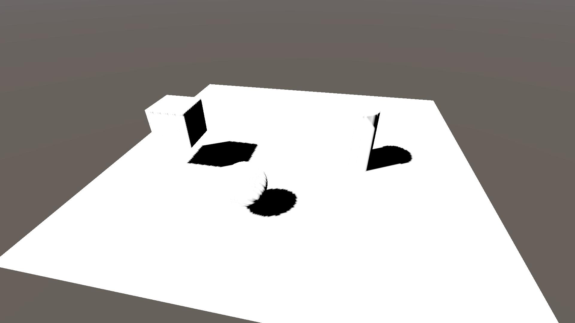
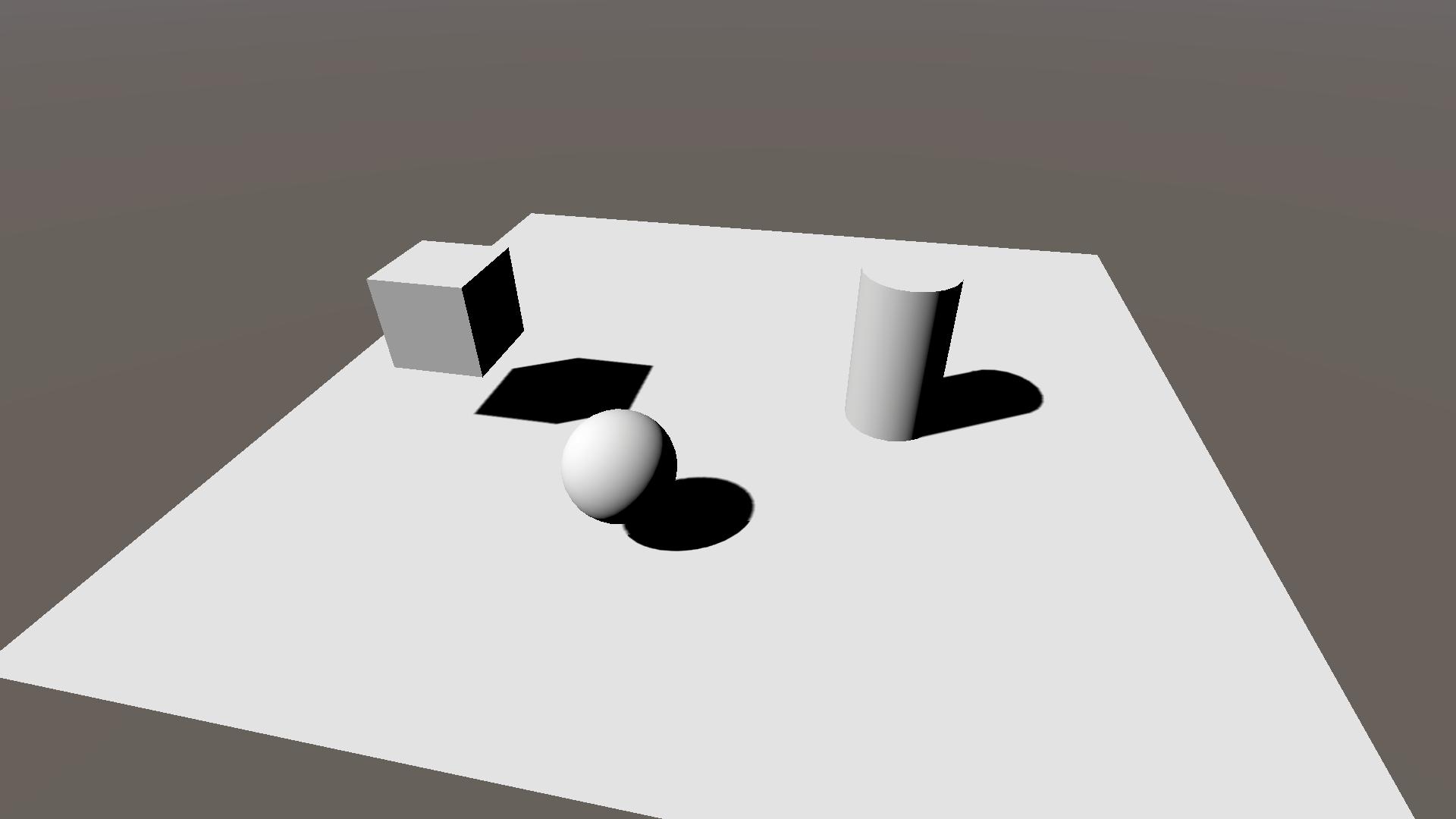
#include "Packages/com.unity.render-pipelines.universal/ShaderLibrary/Lighting.hlsl"Now we can finally see some shadows!

2.2 Pipeline settings
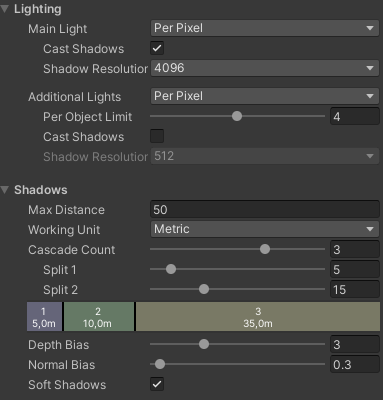
Now that we have our shadow map sampling setup I’ll give a quick overview of the different shadow settings in our URP asset.
The most obvious one is the Shadow Resolution (found under Lighting), where increasing the resolution gives sharper shadows.
Next up is Cascade Count. This splits your shadow map into different sections that are sampled depending on how far away your object is. This way you can have a higher resolution for nearby objects, compared to far away objects. When using this setting you need to define the keyword _MAIN_LIGHT_SHADOWS_CASCADE, like we did in the previous section.

The Soft Shadows tick box changes whether you sample the shadow map only once, or if you take multiple samples to calculate the shadow. Having it on results in softer shadows, as you take neighbouring shadow values into account, but it also decreases your performance as you need to sample the map multiple times.

Finally there are the Depth Bias and Normal Bias. These settings are used to counteract so called shadow-acne or self-shadowing. I won’t go into their details, but you can take a look at Unity’s documentation on them. Note that these biases are applied in the vertex function of the ShadowCaster pass.

2.3 NdotL shadows
As you might have noticed the edge between self-shadowing and the lit surface is quite rough. We can circumvent this by also calculating shadows based on the light direction and the object’s normal direction and taking the minimum of the two shadows.
We calculate if a surface is lit by taking the dot product between the main light direction and object normal direction. This result is often abbreviated as NdotL. Our final shadow value is then simply the minimum of the shadow map and NdotL. Add the highlighted lines and change the value of col to reflect the final shadowing.
float4 shadowCoord = TransformWorldToShadowCoord(IN.posWS);
float shadowMap = MainLightRealtimeShadow(shadowCoord);

float NdotL = saturate(dot(_MainLightPosition.xyz, IN.normalWS));

float combinedShadow = min(NdotL, shadowMap);

float3 col = float3(1, 1, 1) * combinedShadow;
Note that I’ve taken the saturate() of NdotL, this isn’t strictly necessary but I wanted to restrict the shadow values to a 0 to 1 range (0 = shadow, 1 = no shadow).
This basic type of NdotL lighting is often referred to as the Lambert lighting model or Lambertian reflectance model.
2.4 Toon shading
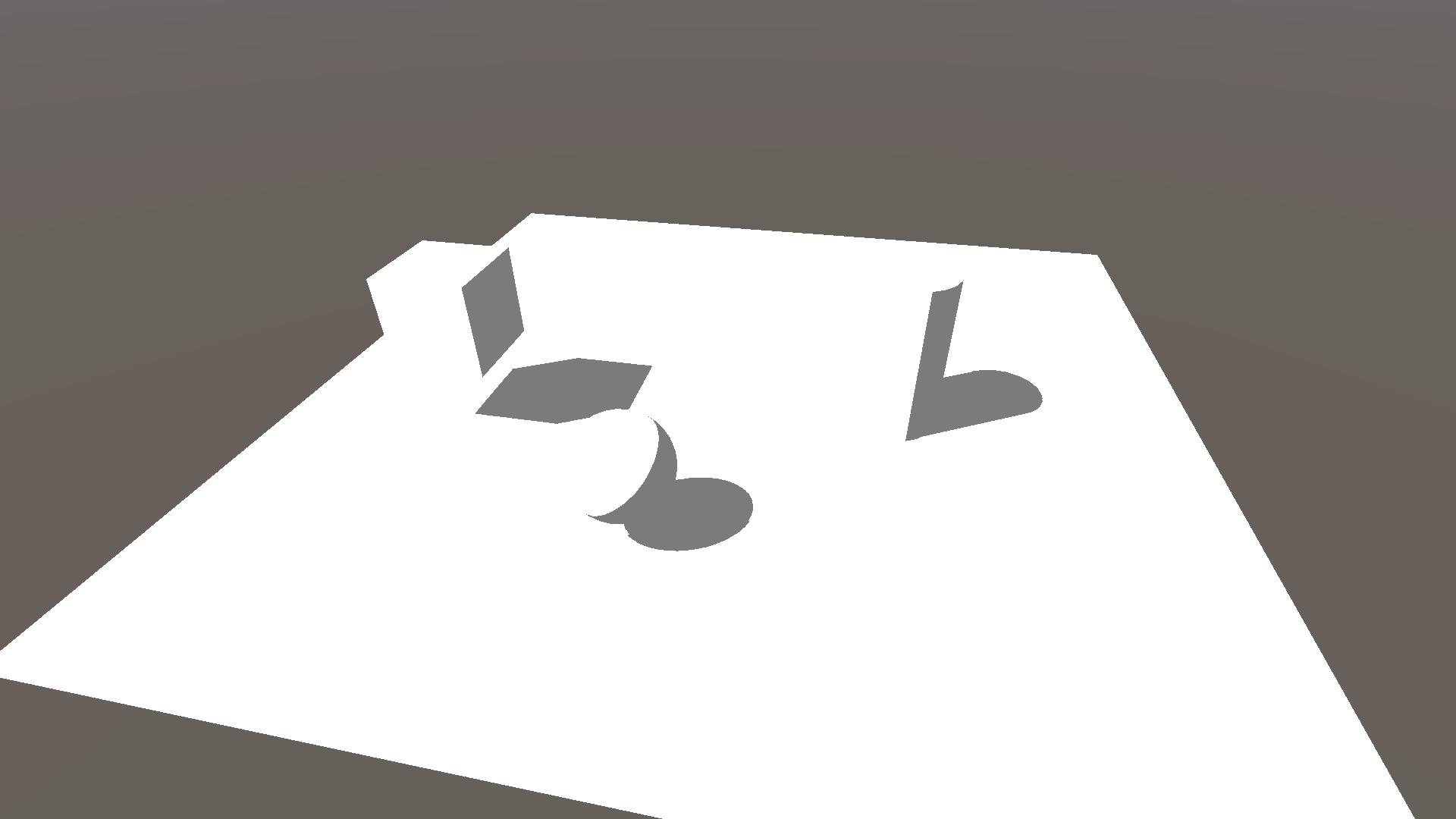
This is not a tutorial on toon shading so we will be using the simplest form of it that is just 1 line of code. We take the combinedShadow and step it with a small number, so that if there is any shadow we consider it to be fully shaded. In addition we’ll add a small number to the result so that the fully shaded area still shows some light and I saturate it to prevent shadowValue from exceeding 1.
Add two properties to control the step and minimum shadow value and declare them just below the vert function. Finally apply them in the frag function. Add/change the highlighted lines from the following code block.
Properties
{
    _ShadowStep ("Shadow step value", Range(0, 1)) = 0.1
    _ShadowMin ("Minimum shadow value", Range(0, 1)) = 0.2
}

...

Varyings vert(Attributes IN)
{}

float _ShadowStep, _ShadowMin;

float4 frag (Varyings IN) : SV_Target
{
    float4 shadowCoord = TransformWorldToShadowCoord(IN.posWS);
    float shadowMap = MainLightRealtimeShadow(shadowCoord);

    float NdotL = saturate(dot(_MainLightPosition.xyz, IN.normalWS));

    float combinedShadow = min(NdotL, shadowMap);
    float shadowValue = saturate(step(_ShadowStep, combinedShadow) + _ShadowMin);

    float3 col = float3(1, 1, 1) * shadowValue;

    return float4(col, 1);
}
3 Edge detection
Now that the shadows are done we can move on to the outlines. These will be drawn by detecting the edges of the shadow, or in more mathematical terms where there is a discontinuity in the shadow, using a convolution matrix.
3.1 Convolution
The most common way of finding discontinuities in an image is using a convolution matrix, also known as a kernel. The convolution is an operation between the image and the kernel, where we take samples from the image, multiply them by the corresponding kernel value and add them together, resulting in a single number.
As an example we look at the image below, which uses a single 3×3 kernel for edge detection (approximation of the Laplace operator). The image has grayscale values ranging from 0 to 1, and the sum is depicted from left to right, top to bottom.
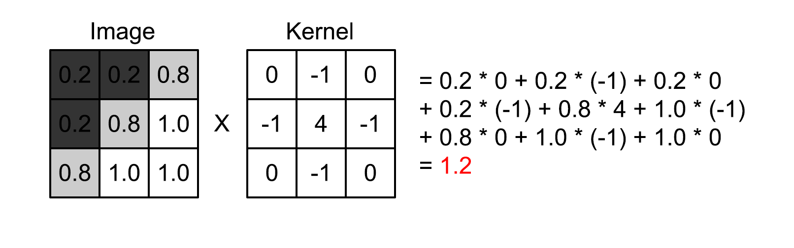
The result is 1.2, and depending on our threshold we would count this result as an edge or not. Note that if all image pixels were white the convolution would result in 0, and the same if all pixels were black or another single value.
For other visual representations of convolution and kernels I recommend these:
- Article by Tommy Tran, specifically the “What is Convolution?” chapter
- Video by Computerphile, 8 minutes showing you how a blur filter works using convolution
3.2 Sobel operator
For our shadow outlines we will be using a different edge detecting operator, namely the Sobel operator. The Sobel operator consists of two kernels, one for detecting the gradient (rate of change) in the x-direction and one for the y-direction. The kernels look as follows.
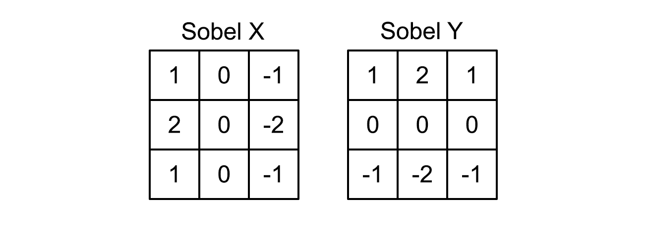
Note that these are weighted gradients, the values near the centre are higher and thus influence the result more than the outer values.
In order to get to a single value we take the magnitude of the kernel results \(S_X\) and \(S_Y\), resulting in a single value \(S = \sqrt{S_X^2 + S_Y^2}\).
3.3 Implementation
In order to implement the convolution we’ll be adding 3 arrays with 9 entries, corresponding to our 3×3 region. The first array is for the sample points, including the centre at (0, 0), the second and third are the x-Sobel and y-Sobel kernels respectively. Add the following lines below the vert function, but before the frag function.
// 3x3 sample points
static float2 sobelSamplePoints[9] = {
    float2(-1, 1), float2(0, 1), float2(1, 1),
    float2(-1, 0), float2(0, 0), float2(1, 0),
    float2(-1, -1), float2(0, -1), float2(1, -1)
};

static float sobelXKernel[9] = {
    1, 0, -1,
    2, 0, -2,
    1, 0, -1
};

static float sobelYKernel[9] = {
    1, 2, 1,
    0, 0, 0,
    -1, -2, -1
};
Now in order to calculate the convolution we’ll add a separate function that we can call from the frag function, we’ll call it ShadowSobelOperator.
Because we’re going to sample the shadow map at 9 points, the pixel we’re rendering and its 8 neighbouring pixels, we first need to get the texel size (i.e. the distance between each pixel). Next we do a for loop over all 9 entries of the sobelSamplePoints array and enumerate the convolution values of the x- and y-Sobel. Finally we return the magnitude by taking the square root of the sum of squares. Add the following function below the arrays.
// Calculate the Sobel operator of the shadowmap
float ShadowSobelOperator(float4 shadowCoord)
{
    // Get the shadowmap texelsize
    ShadowSamplingData shadowSamplingData = GetMainLightShadowSamplingData();
    float4 shadowMap_TexelSize = shadowSamplingData.shadowmapSize;

    // Initialise results
    float sobelX = 0;
    float sobelY = 0;

    // Loop over sample points
    [unroll] for (int i = 0; i < 9; i++)
    {
        // Sample shadowmap
        float shadowImage = MainLightRealtimeShadow(float4(shadowCoord.xy + sobelSamplePoints[i] * shadowMap_TexelSize.xy, shadowCoord.zw));

        // Sum the convolution values
        sobelX += shadowImage * sobelXKernel[i];
        sobelY += shadowImage * sobelYKernel[i];
    }

    // Return the magnitude
    return sqrt(sobelX * sobelX + sobelY * sobelY);
}
The ShadowSobelOperator will return values greater than 0 if there is a change in shadow map value. In order to show the shadow outline we’ll add a property for outline colour and lerp between this and our previously shaded col depending on the outcome of the ShadowSobelOperator. Add the highlighted lines for the property, its declaration and add the two lines in the frag function to find the outline and lerp the colour.
Properties
{
    _ShadowStep ("Shadow step value", Range(0, 1)) = 0.1
    _ShadowMin ("Minimum shadow value", Range(0, 1)) = 0.2
    _OutlineColor ("Outline color", Color) = (0, 0, 0, 1)
}

...

float _ShadowStep, _ShadowMin;
float3 _OutlineColor;

...

float4 frag (Varyings IN) : SV_Target
{
    ...

    float shadowOutlineMask = SobelOperator(shadowCoord);

    float3 col = float3(1, 1, 1) * shadowValue;
    col = lerp(col, _OutlineColor, saturate(shadowOutlineMask));

    return float4(col, 1);
}
Soooo, this doesn’t look too great yet because we have our rough edges back and the edge width isn’t consistent (see the shadow of the sphere on the ground). The rough edges is simply how the shadow map looks and something we’ll remove through masking. The inconsistent width is caused by the shadow cascades, which we’ll lessen using the cascade index. But first let’s add a way of changing the width of our outlines through dilation.
3.3.1 Dilation
The idea of dilation is that instead of sampling a 3×3 area directly surrounding the centre pixel we expand (dilate) the 8 surrounding sample points. The concept is best shown in an illustration, here red are the pixels that are sampled.
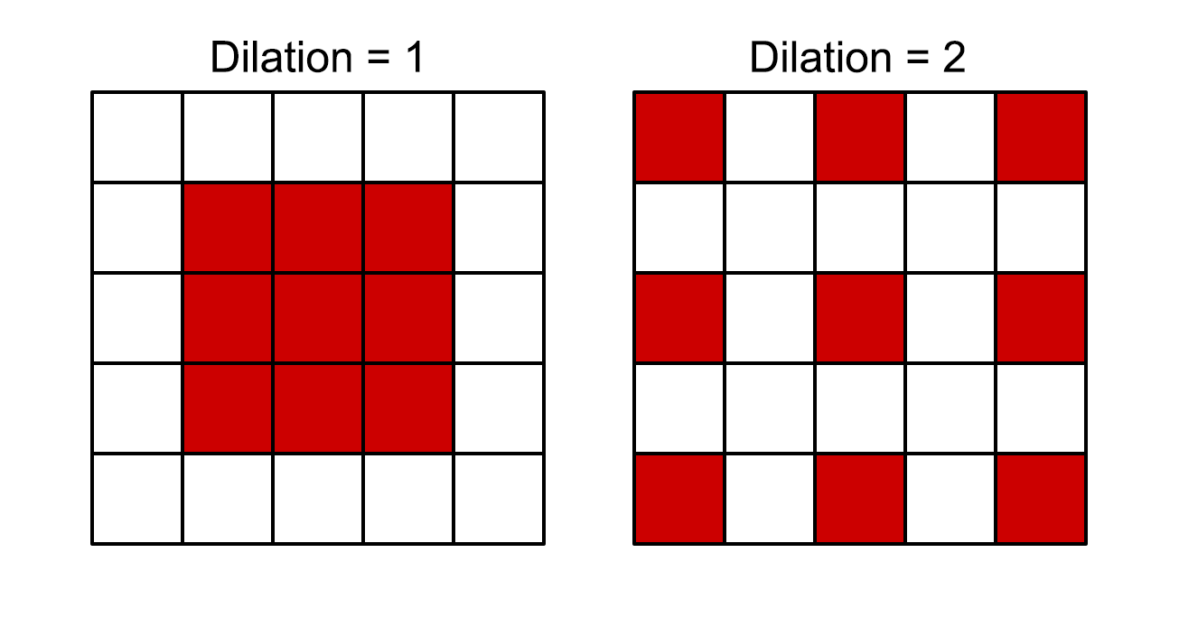
Dilation will increase the width of the outlines because we sample further away. Because we still only do 9 samples it won’t impact performance, but the edge detection will be less accurate.
We’ll add a property to the shader to control the amount of dilation. Add/change the highlighted lines to add the property and declare it.
Properties
{
    _ShadowStep ("Shadow step value", Range(0, 1)) = 0.1
    _ShadowMin ("Minimum shadow value", Range(0, 1)) = 0.2
    _OutlineColor ("Outline color", Color) = (0, 0, 0, 1)
    _ShadowDilation ("Shadow dilation", Range(0, 10)) = 1
}

...

float _ShadowStep, _ShadowMin, _ShadowDilation;
float3 _OutlineColor;
Note that the dilation can also be set to 0, where only the centre pixel is sampled and thus no outline is drawn.
Implementing the dilation is as simple as multiplying the sample points by the _ShadowDilation. Change the highlighted lines in the ShadowSobelOperator function and frag function.
float ShadowSobelOperator(float4 shadowCoord, float dilation)
{
// Get the shadowmap texelsize
ShadowSamplingData shadowSamplingData = GetMainLightShadowSamplingData();
float4 shadowMap_TexelSize = shadowSamplingData.shadowmapSize;
// Initialise results
float sobelX = 0;
float sobelY = 0;
// Loop over sample points
[unroll] for (int i = 0; i < 9; i++)
{
// Sample shadowmap
float shadowImage = MainLightRealtimeShadow(float4(shadowCoord.xy + sobelSamplePoints[i] * dilation * shadowMap_TexelSize.xy, shadowCoord.zw));
// Sum the convolution values
sobelX += shadowImage * sobelXKernel[i];
sobelY += shadowImage * sobelYKernel[i];
}
// Return the magnitude
return sqrt(sobelX * sobelX + sobelY * sobelY);
}
float4 frag (Varyings IN) : SV_Target
{
...
float shadowOutlineMask = ShadowSobelOperator(shadowCoord, _ShadowDilation);
float3 col = float3(1, 1, 1) * shadowValue;
col = lerp(col, _OutlineColor, saturate(shadowOutlineMask));
return float4(col, 1);
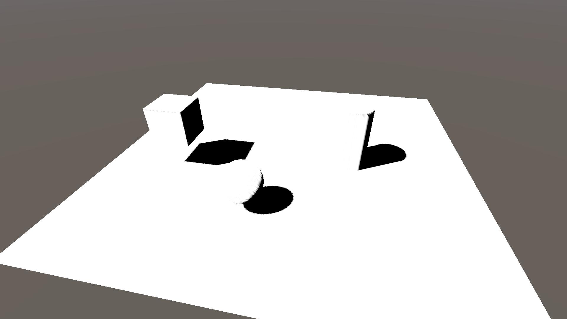
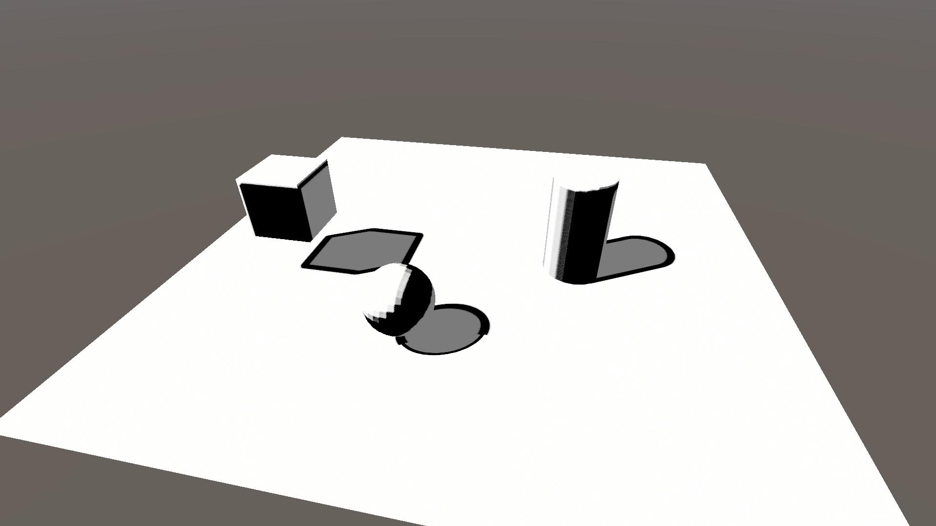
}If you look at the result below (with _ShadowOutlines = 4) it seems to be getting worse, and it is, but I promise that by the end it will look better.
3.3.2 Cascade index
Now that we have dilation, we can alter it depending on the cascade index. The cascade index increases the further away the shadows are and we can use that to decrease the dilation and have more consistent line width.
The best part is that we already know the cascade index, as it is the w-component of the shadowCoord. We’ll implement it by dividing the dilation by 2 to the power of the cascade index (the index starts at 0). Change the following line in the frag function.
float shadowOutlineMask = ShadowSobelOperator(shadowCoord, _ShadowDilation / pow(2, shadowCoord.w));While not perfect you can see that the shadow outlines are more consistent over the different cascades. The choice of dividing by a power of two is rather arbitrary and you could play around using different powers or functions to get better results.

Note that through this division the dilation can get very low, where near 0 the outline would disappear. If you want you can limit the dilation to be at least 1 through a min(1, dilation) function.
3.3.3 Masking
Although the previous steps have improved the shadow outlines, the self-shadowing outlines don’t look good. Unfortunately I’ve not yet found a way to do them proper, and thus we will only mask them away.
We’ll be masking it so that there are shadow outlines where the shadow map has strong enough shadows, but not where there are NdotL shadows. Add the highlighted lines in the frag function.
float shadowOutlineMask = ShadowSobelOperator(shadowCoord, _ShadowDilation / pow(2, shadowCoord.w));
// Mask, 1 = shadowmap shadows, 0 = no shadowmap shadows
shadowOutlineMask *= (1 - step(_ShadowStep, shadowMap));
// Mask, 1 = no NdotL shadows, 0 = NdotL shadows
shadowOutlineMask *= step(_ShadowStep, NdotL);
float3 col = float3(1, 1, 1) * shadowValue;
col = lerp(col, _OutlineColor, saturate(shadowOutlineMask));
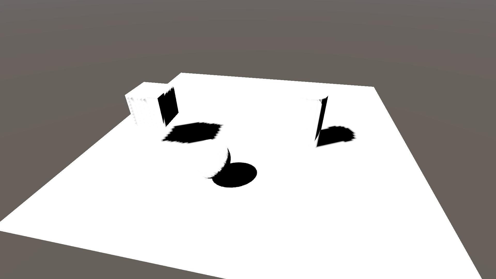
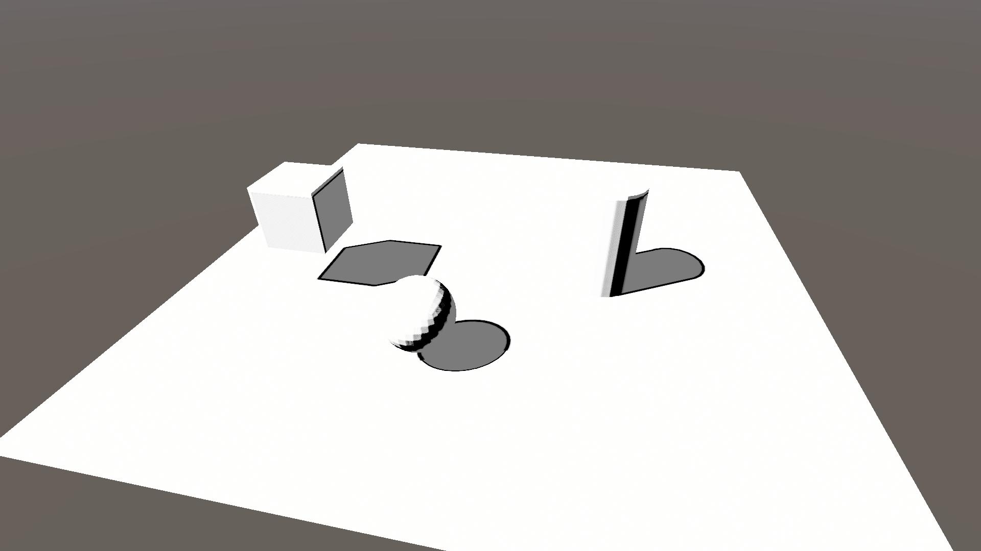
return float4(col, 1);In the resulting image below I’ve added another cube, so that you can see that the shadow casted by the cube onto the sphere has an outline that stops where the sphere is shaded by it’s NdotL value.
4 Conclusion
Congratulations, you’ve reached the end of the tutorial! You now know how to:
- sample the shadow map in URP,
- change the pipeline settings,
- calculate NdotL shadows,
- apply the Lambert lighting model,
- do some simplistic toon shading,
- do convolution and edge detection,
- and finally how to make shadow outlines.
Thank you very much for reading and I hope you learned something new. If you want to support me financially you can do so using my ko-fi page. You can also check out my twitter for more shader work and other things that might not make it to the site.