Supermassive black hole tutorial
Due to the interest in my supermassive black hole (SMBH) shader I’ve decided to write a tutorial on it. Note that it is my first tutorial, and thus the format will be a bit janky as I try to figure out a good way of communicating my process. Also, I’m not a professional when it comes to writing shaders and thus do not take any of this as best practices or the “correct” way of making them.
In this tutorial I will walk you through the individual components and process of recreating my SMBH shader. It combines raymarching and the law of gravity to simulate the iconic visualisation of black holes.
This tutorial was made with Unity 2020.3.1f1 and the Universal Render Pipeline (URP). The shaders are written in HLSL, but note that the general concept can be applied to any shader environment. You can get the project files here, including the initial and finished shader.
Acknowledgements
Before I get into the meat of things I would like to acknowledge some of my inspirations for this specific tutorial and add some general acknowledgements for tutorials that helped me get here.
- The artistic aspects and overal visuals were mainly guided by this stunning visualisation done by NASA.
- The math behind finding the intersections of cylinders and spheres are based on these slides by Prof. Denis Zorin of the New York University and this page by Victor Li respectively.
- In order to change the HDR color in shader I’ve used code from this forum post by Ben Golus
In more general terms I would like to thank the following tutorial creators
- Alan Zucconi, Joyce (Minions Art) and Jasper Flick (Catlike Coding), whose tutorials helped me get into shader programming. Obviously the format of this tutorial is also inspired by theirs.
- Sebastian Lague and specifically his coding adventure on clouds, which is what got me started on raymarching shaders.
Contents
1 Shader setup
If you’re using the project files you can skip this section and start at 1.1 Ray information by opening SMBH_Initial.
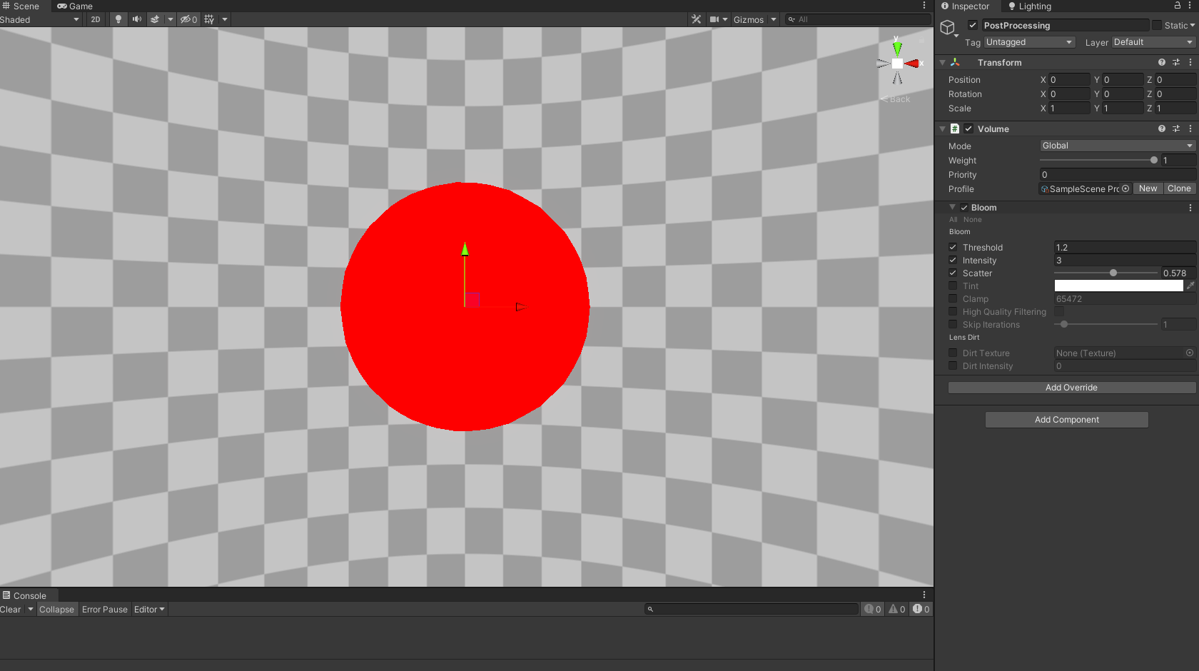
This shader will be written as a HLSL program and applied to the basic Unity sphere. In our scene we will only have a camera, a post-processing volume (for some bloom) and a Unity sphere with the scale set to (5, 5, 5) to which we will apply our shader. Don’t forget to set post processing to true on our camera, like I always do.
The basic shader setup will look as follows from the code block. It doesn’t do much yet but it contains all the vertex information we’ll need, most notably the centre and scale of our sphere gameObject. The fragment shader simply returns a red color for now. Note that we’ve also set the culling to front and the queue to transparent, this will be necessary if we want to move into the black holes space and to get data on what’s behind it later.
I’ve also included the opaque texture, a rendering of the screen before transparent objects are drawn, which will be used to distort the area around our black hole. However, for this to work in URP we will need to activate the opaque texture in the Universal Render Pipeline Asset, found in the settings folder when we create a new URP project.
Shader "KelvinvanHoorn/SMBH"
{
    Properties
    {
    }
    SubShader
    {
        Tags { "RenderType" = "Transparent" "RenderPipeline" = "UniversalRenderPipeline" "Queue" = "Transparent" }
        Cull Front

        Pass
        {
            HLSLPROGRAM
            #pragma vertex vert
            #pragma fragment frag

            #include "Packages/com.unity.render-pipelines.universal/ShaderLibrary/Core.hlsl"
            #include "Packages/com.unity.render-pipelines.universal/ShaderLibrary/DeclareOpaqueTexture.hlsl"

            static const float maxFloat = 3.402823466e+38;

            struct Attributes
            {
                float4 posOS    : POSITION;
            };

            struct v2f
            {
                float4 posCS        : SV_POSITION;
                float3 posWS        : TEXCOORD0;

                float3 centre       : TEXCOORD1;
                float3 objectScale  : TEXCOORD2;
            };

            v2f vert(Attributes IN)
            {
                v2f OUT = (v2f)0;

                VertexPositionInputs vertexInput = GetVertexPositionInputs(IN.posOS.xyz);

                OUT.posCS = vertexInput.positionCS;
                OUT.posWS = vertexInput.positionWS;

                // Object information, based upon Unity's shadergraph library functions
                OUT.centre = UNITY_MATRIX_M._m03_m13_m23;
                OUT.objectScale = float3(length(float3(UNITY_MATRIX_M[0].x, UNITY_MATRIX_M[1].x, UNITY_MATRIX_M[2].x)),
                                length(float3(UNITY_MATRIX_M[0].y, UNITY_MATRIX_M[1].y, UNITY_MATRIX_M[2].y)),
                                length(float3(UNITY_MATRIX_M[0].z, UNITY_MATRIX_M[1].z, UNITY_MATRIX_M[2].z)));

                return OUT;
            }

            float4 frag (v2f IN) : SV_Target
            {
                return float4(1,0,0,1);
            }
            ENDHLSL
        }
    }
}
1.1 Ray information
In order to start raytracing we need to know where our ray starts (to calculate distances) and what direction it has. We determine this using the camera’s position, as our rays travel from there, by adding the highlighted code to the frag function.
float4 frag (v2f IN) : SV_Target
{
    // Initial ray information
    float3 rayOrigin = _WorldSpaceCameraPos;
    float3 rayDir = normalize(IN.posWS - _WorldSpaceCameraPos);

    return float4(1,0,0,1);
}
Before we tackle a disc let’s first raytrace an outer sphere to which we can confine any further raytracing. For this we want to know when our ray intersects a sphere. To do this add the following function between the vert and frag functions. I won’t go into the details of this function here, but you can read up on it following the commented link, or look at my other tutorial that is all about finding intersections.
// Based upon https://viclw17.github.io/2018/07/16/raytracing-ray-sphere-intersection/#:~:text=When%20the%20ray%20and%20sphere,equations%20and%20solving%20for%20t.
// Returns dstToSphere, dstThroughSphere
// If inside sphere, dstToSphere will be 0
// If ray misses sphere, dstToSphere = max float value, dstThroughSphere = 0
// Given rayDir must be normalized
float2 intersectSphere(float3 rayOrigin, float3 rayDir, float3 centre, float radius) {

    float3 offset = rayOrigin - centre;
    const float a = 1;
    float b = 2 * dot(offset, rayDir);
    float c = dot(offset, offset) - radius * radius;

    float discriminant = b * b - 4 * a*c;
    // No intersections: discriminant < 0
    // 1 intersection: discriminant == 0
    // 2 intersections: discriminant > 0
    if (discriminant > 0) {
        float s = sqrt(discriminant);
        float dstToSphereNear = max(0, (-b - s) / (2 * a));
        float dstToSphereFar = (-b + s) / (2 * a);

        if (dstToSphereFar >= 0) {
            return float2(dstToSphereNear, dstToSphereFar - dstToSphereNear);
        }
    }
    // Ray did not intersect sphere
    return float2(maxFloat, 0);
}
Now to use this function we’ll need to add some extra code to the frag function. First we determine the radius of our raytraced sphere, let’s set it to the smallest scale of our sphere gameObject. By passing the information of the raytracing sphere and our ray we can determine if, how far, and how long they intersect.
In order to show the raytraced sphere we’re going to lerp between a solid color and the opaque texture. To do this we calculate the appropriate UV of our screen to sample the opaque texture and set our lerp interpolator (transmittance) to 1 if we find an intersection. Add the highlighted code just below our ray information in the frag function and change the return to our new lerped color.
float3 rayOrigin = _WorldSpaceCameraPos;
float3 rayDir = normalize(IN.posWS - _WorldSpaceCameraPos);
float sphereRadius = 0.5 * min(min(IN.objectScale.x, IN.objectScale.y), IN.objectScale.z);
float2 outerSphereIntersection = intersectSphere(rayOrigin, rayDir, IN.centre, sphereRadius);
// Raymarching information
float transmittance = 0;
// Ray intersects with the outer sphere
if(outerSphereIntersection.x < maxFloat)
transmittance = 1;
float2 screenUV = IN.posCS.xy / _ScreenParams.xy;
float3 backgroundCol = SampleSceneColor(screenUV);
float3 col = lerp(backgroundCol, float3(1,0,0), transmittance);
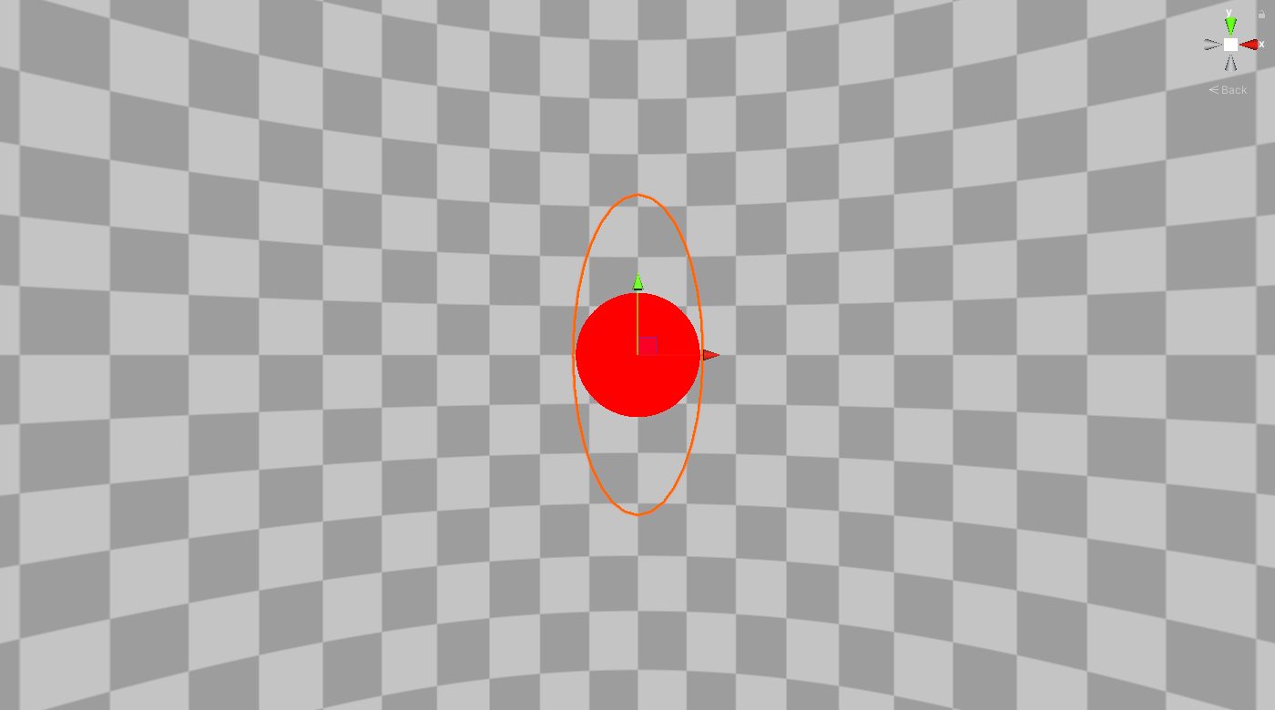
return float4(col,1);To see if it works we can change one of the scales of the sphere gameObject and see that the raytraced sphere changes its radius to the smallest scale. Congratulations, we made our first raytracing shader.
2 Raytracing a disc
Raytracing a disc? I thought we were going to make a black hole? Well, you can’t actually see a black hole, you can only see how it affects its environment. To do that we’ll be making an accretion disc (a disc of hot matter that spins around the black hole).
To raytrace our disc we need three more intersection functions, one for an infinite cylinder, one for an infinite plane and one for the disc (which depends on the first two). Add the following three functions below the intersectSphere function. Again I wont go over the details of these functions here, but you can read up on it following the commented links, or look at my other tutorial that is all about finding intersections.
// Based upon https://mrl.cs.nyu.edu/~dzorin/rend05/lecture2.pdf
float2 intersectInfiniteCylinder(float3 rayOrigin, float3 rayDir, float3 cylinderOrigin, float3 cylinderDir, float cylinderRadius)
{
    float3 a0 = rayDir - dot(rayDir, cylinderDir) * cylinderDir;
    float a = dot(a0,a0);

    float3 dP = rayOrigin - cylinderOrigin;
    float3 c0 = dP - dot(dP, cylinderDir) * cylinderDir;
    float c = dot(c0,c0) - cylinderRadius * cylinderRadius;

    float b = 2 * dot(a0, c0);

    float discriminant = b * b - 4 * a * c;

    if (discriminant > 0) {
        float s = sqrt(discriminant);
        float dstToNear = max(0, (-b - s) / (2 * a));
        float dstToFar = (-b + s) / (2 * a);

        if (dstToFar >= 0) {
            return float2(dstToNear, dstToFar - dstToNear);
        }
    }
    return float2(maxFloat, 0);
}

// Based upon https://mrl.cs.nyu.edu/~dzorin/rend05/lecture2.pdf
float intersectInfinitePlane(float3 rayOrigin, float3 rayDir, float3 planeOrigin, float3 planeDir)
{
    float a = 0;
    float b = dot(rayDir, planeDir);
    float c = dot(rayOrigin, planeDir) - dot(planeDir, planeOrigin);

    float discriminant = b * b - 4 * a*c;

    return -c/b;
}

// Based upon https://mrl.cs.nyu.edu/~dzorin/rend05/lecture2.pdf
float intersectDisc(float3 rayOrigin, float3 rayDir, float3 p1, float3 p2, float3 discDir, float discRadius, float innerRadius)
{
    float discDst = maxFloat;
    float2 cylinderIntersection = intersectInfiniteCylinder(rayOrigin, rayDir, p1, discDir, discRadius);
    float cylinderDst = cylinderIntersection.x;

    if(cylinderDst < maxFloat)
    {
        float finiteC1 = dot(discDir, rayOrigin + rayDir * cylinderDst - p1);
        float finiteC2 = dot(discDir, rayOrigin + rayDir * cylinderDst - p2);

        // Ray intersects with edges of the cylinder/disc
        if(finiteC1 > 0 && finiteC2 < 0 && cylinderDst > 0)
        {
            discDst = cylinderDst;
        }
        else
        {
            float radiusSqr = discRadius * discRadius;
            float innerRadiusSqr = innerRadius * innerRadius;

            float p1Dst = max(intersectInfinitePlane(rayOrigin, rayDir, p1, discDir), 0);
            float3 q1 = rayOrigin + rayDir * p1Dst;
            float p1q1DstSqr = dot(q1 - p1, q1 - p1);

            // Ray intersects with lower plane of cylinder/disc
            if(p1Dst > 0 && p1q1DstSqr < radiusSqr && p1q1DstSqr > innerRadiusSqr)
            {
                if(p1Dst < discDst)
                {
                    discDst = p1Dst;
                }
            }

            float p2Dst = max(intersectInfinitePlane(rayOrigin, rayDir, p2, discDir), 0);
            float3 q2 = rayOrigin + rayDir * p2Dst;
            float p2q2DstSqr = dot(q2 - p2, q2 - p2);

            // Ray intersects with upper plane of cylinder/disc
            if(p2Dst > 0 && p2q2DstSqr < radiusSqr && p2q2DstSqr > innerRadiusSqr)
            {
                if(p2Dst < discDst)
                {
                    discDst = p2Dst;
                }
            }
        }
    }

    return discDst;
}
In order to define our disc we’ll want to know its inner and outer radius, width, direction and where the top and bottom caps are. The first three we’ll define through properties, add the following properties near the top of the file and declare them just below the vert function (but before the other functions).
Properties
{
    _DiscWidth ("Width of the accretion disc", float) = 0.1
    _DiscOuterRadius ("Object relative outer disc radius", Range(0,1)) = 1
    _DiscInnerRadius ("Object relative disc inner radius", Range(0,1)) = 0.25
}

...
vert(){}
float _DiscWidth;
float _DiscOuterRadius;
float _DiscInnerRadius;
The disc’s direction and the position of the caps we’ll calculate in the frag function, where we set the direction equal to the local y-axis of our sphere gameObject. Add the highlighted lines just below the outerSphereIntersection. Here p1 and p2 are the bottom and top cap positions respectively.
float2 outerSphereIntersection = intersectSphere(IN.centre, sphereRadius, rayOrigin, rayDir);
// Disc information, direction is objects rotation
float3 discDir = normalize(mul(unity_ObjectToWorld, float4(0,1,0,0)).xyz);
float3 p1 = IN.centre - 0.5 * _DiscWidth * discDir;
float3 p2 = IN.centre + 0.5 * _DiscWidth * discDir;
float discRadius = sphereRadius * _DiscOuterRadius;
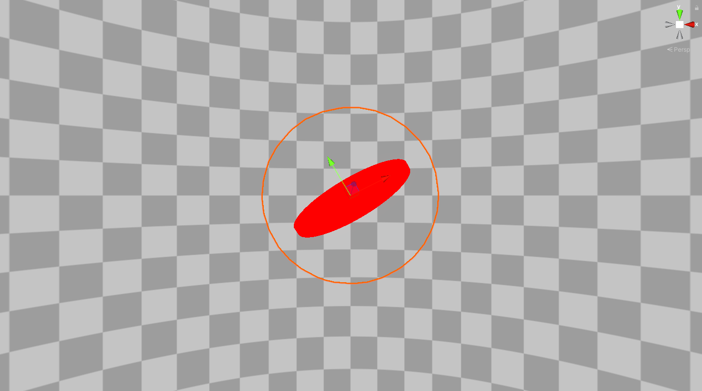
float innerRadius = sphereRadius * _DiscInnerRadius;Now in order to raytrace our disc we’ll change our transmittance value only if it both intersects with the outer sphere and with the disc. Go back to the frag function and change the commented code into the new highlighted code. We should now be able to see a red disc of which we can change the radius and width through properties and the direction by rotating the sphere gameObject.
// Ray intersects with the outer sphere
//if(outerSphereIntersection.x < maxFloat)
//  transmittance = 1;

// Ray intersects with the outer sphere
if(outerSphereIntersection.x < maxFloat)
{
    float discDst = intersectDisc(rayOrigin, rayDir, p1, p2, discDir, discRadius, innerRadius);
    if(discDst < maxFloat)
    {
        transmittance = 1;
    }
}
2.1 UV mapping
So we have a disc, but a simple red disc is a bit boring. In order to apply some texture to it we will have to define our UV space. Because we’re working with a disc that will be thin I’ve chosen to make a polar coordinate mapping of the disc. This is a 2D mapping where the U will be our radial distance from the centre, and the V will be the angular distance with respect to some vector tangent to the disc. Note that our texture will thus be stretched along the width, but this is no problem as it will be a very thin disc.
Before we do any mapping we need to get some more information from our raytraced disc. We need to know where our ray intersects the disc, let’s call it the sample position. Add the samplePos variable to our Ray information and change it where we change the transmittance.
//Ray information
float transmittance = 0;
float3 samplePos = float3(maxFloat, 0, 0);

...
if(discDst < maxFloat)
{
    transmittance = 1;
    samplePos = rayOrigin + rayDir * discDst;
}
In order to get the UV we’ll be adding two new functions, remap and discUV. The remap function simply remaps a float from a given range to a new range. The discUV function calculates our polar coordinates and remaps them to a 0 to 1 range. Add these two functions above the frag function.
float remap(float v, float minOld, float maxOld, float minNew, float maxNew) {
    return minNew + (v - minOld) * (maxNew - minNew) / (maxOld - minOld);
}

float2 discUV(float3 planarDiscPos, float3 discDir, float3 centre, float radius)
{
    float3 planarDiscPosNorm = normalize(planarDiscPos);
    float sampleDist01 = length(planarDiscPos) / radius;

    float3 tangentTestVector = float3(1,0,0);
    if(abs(dot(discDir, tangentTestVector)) >= 1)
        tangentTestVector = float3(0,1,0);

    float3 tangent = normalize(cross(discDir, tangentTestVector));
    float3 biTangent = cross(tangent, discDir);
    float phi = atan2(dot(planarDiscPosNorm, tangent), dot(planarDiscPosNorm, biTangent)) / PI;
    phi = remap(phi, -1, 1, 0, 1);

    // Radial distance
    float u = sampleDist01;
    // Angular distance
    float v = phi;

    return float2(u,v);
}
In order to check if everything is working alright we’ll display the UV as a color on the disc. But before we do that we also need retrieve the planar part of our samplePos before calling discUV in the frag function. After the raytracing but before the opaque texture section add the highlighted lines and change the col lerp.
if(outerSphereIntersection.x < maxFloat)
{}

float2 uv = float2(0,0);
float3 planarDiscPos = float3(0,0,0);
if(samplePos.x < maxFloat)
{
    planarDiscPos = samplePos - dot(samplePos - IN.centre, discDir) * discDir - IN.centre;
    uv = discUV(planarDiscPos, discDir, IN.centre, discRadius);
}

float2 screenUV = IN.posCS.xy / _ScreenParams.xy;

...
float3 col = lerp(backgroundCol, float3(uv.x, uv.y, 0), transmittance);
return float4(col,1);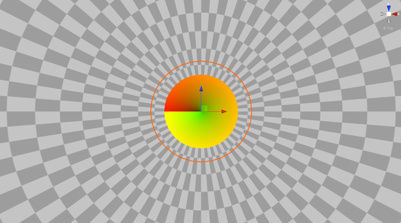
Note that there is an abrupt change in value on the left. This is caused by the atan2 function in our discUV function. This discontinuity will cause problems when using mipmaps in our textures. Because of the scope of this tutorial we won’t fix it and simply turn off mipmaps in our texture later on. However, if you are interested I would recommend looking at this recent article by Ben Golus that discusses exactly this problem.
2.2 Applying a texture
If your using the project files you can find the texture in the textures folder with the name noiseTexture.
For the texture I’ll use some tileable Perlin noise but it can be anything we want. We can generate such a texture on this website, made by Mark McKay. I’ve changed my cell size to 32, the levels to 3 and attenuation to 2. Be sure to turn off Generate Mip Maps once we’ve imported the texture to Unity.
Now to get our texture add it to the properties and declare them just below the vert function, similar to our disc properties.
Properties
{
    ...
    _DiscTex ("Disc texture", 2D) = "white" {}
}

...
vert(){}
...
Texture2D _DiscTex;
SamplerState sampler_DiscTex;
float4 _DiscTex_ST;
Now we can sample this texture in the frag function and adjust our transmittance accordingly by adding the highlighted code after we’ve set the UV. Note that we multiply uv by _DiscTex_ST.xy, this way we can use the tiling properties in the Unity editor to tile our texture. Be sure to keep the Y tiling an integer, otherwise our texture won’t tile seamlessly. Also, don’t forget to actually set the texture in the Unity editor.
if(samplePos.x < maxFloat)
{
    planarDiscPos = samplePos - dot(samplePos - IN.centre, discDir) * discDir - IN.centre;
    uv = discUV(planarDiscPos, discDir, IN.centre, discRadius);
}
float texCol = _DiscTex.SampleLevel(sampler_DiscTex, uv * _DiscTex_ST.xy, 0).r;

float2 screenUV = IN.posCS.xy / _ScreenParams.xy;
float3 backgroundCol = SampleSceneColor(screenUV);

transmittance *= texCol;
float3 col = lerp(backgroundCol, float3(1,0,0), transmittance);
return float4(col,1);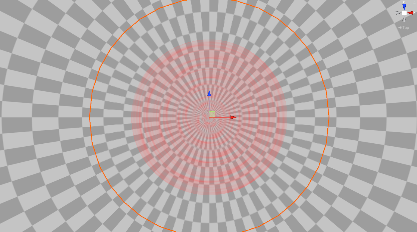
2.3 Texture animation
Our accretion disc should be spinning, so let’s add that. Due to our polar coordinate UV this is actually really simple, we just increase our V over time. To control this let’s add a speed property and add it to our V coordinate in the frag function.
Properties{
    ...
    _DiscSpeed ("Disc rotation speed", float) = 2
}

...
vert(){}
...
float _DiscSpeed;

...
if(samplePos.x < maxFloat)
{
    planarDiscPos = samplePos - dot(samplePos - IN.centre, discDir) * discDir - IN.centre;
    uv = discUV(samplePos, discDir, IN.centre, discRadius);
    uv.y += _Time.x * _DiscSpeed;
}2.4 Adding color and physics
Our red disc is looking a lot better, but it’s a bit hard to see and a bit red. Let’s do some interesting things with the color, like change it’s hue and intensity depending on the distance to the centre and alter its intensity further based on to the Doppler beaming shown in the NASA visualisation.
Let’s start as usual by adding some new properties to control our effects and declare them as well.
Properties{
    ...
    [HDR]_DiscColor ("Disc main color", Color) = (1,0,0,1)
    _DopplerBeamingFactor ("Doppler beaming effect factor", float) = 66
    _HueRadius ("Hue shift start radius", Range(0,1)) = 0.75
    _HueShiftFactor ("Hue shifting factor", float) = -0.03
}

...
vert(){}
...
float4 _DiscColor;
float _DopplerBeamingFactor;
float _HueRadius;
float _HueShiftFactor;
In order to do these hue and intensity changes we’ll be adding a bunch of helper functions of which I shall spare you the details. Add the following code just below the discUV function.
// Based upon UnityCG.cginc, used in hdrIntensity
float3 LinearToGammaSpace (float3 linRGB)
{
    linRGB = max(linRGB, float3(0.f, 0.f, 0.f));
    // An almost-perfect approximation from http://chilliant.blogspot.com.au/2012/08/srgb-approximations-for-hlsl.html?m=1
    return max(1.055h * pow(linRGB, 0.416666667h) - 0.055h, 0.h);
}

// Based upon UnityCG.cginc, used in hdrIntensity
float3 GammaToLinearSpace (float3 sRGB)
{
    // Approximate version from http://chilliant.blogspot.com.au/2012/08/srgb-approximations-for-hlsl.html?m=1
    return sRGB * (sRGB * (sRGB * 0.305306011f + 0.682171111f) + 0.012522878f);
}

// Based upon https://forum.unity.com/threads/how-to-change-hdr-colors-intensity-via-shader.531861/
float3 hdrIntensity(float3 emissiveColor, float intensity)
{
    // if not using gamma color space, convert from linear to gamma
    #ifndef UNITY_COLORSPACE_GAMMA
    emissiveColor.rgb = LinearToGammaSpace(emissiveColor.rgb);
    #endif
    // apply intensity exposure
    emissiveColor.rgb *= pow(2.0, intensity);
    // if not using gamma color space, convert back to linear
    #ifndef UNITY_COLORSPACE_GAMMA
    emissiveColor.rgb = GammaToLinearSpace(emissiveColor.rgb);
    #endif

    return emissiveColor;
}

// Based upon Unity's shadergraph library functions
float3 RGBToHSV(float3 c)
{
    float4 K = float4(0.0, -1.0 / 3.0, 2.0 / 3.0, -1.0);
    float4 p = lerp(float4(c.bg, K.wz), float4(c.gb, K.xy), step(c.b, c.g));
    float4 q = lerp(float4(p.xyw, c.r), float4(c.r, p.yzx), step(p.x, c.r));
    float d = q.x - min(q.w, q.y);
    float e = 1.0e-10;
    return float3(abs(q.z + (q.w - q.y) / (6.0 * d + e)), d / (q.x + e), q.x);
}

// Based upon Unity's shadergraph library functions
float3 HSVToRGB(float3 c)
{
    float4 K = float4(1.0, 2.0 / 3.0, 1.0 / 3.0, 3.0);
    float3 p = abs(frac(c.xxx + K.xyz) * 6.0 - K.www);
    return c.z * lerp(K.xxx, saturate(p - K.xxx), c.y);
}

// Based upon Unity's shadergraph library functions
float3 RotateAboutAxis(float3 In, float3 Axis, float Rotation)
{
    float s = sin(Rotation);
    float c = cos(Rotation);
    float one_minus_c = 1.0 - c;

    Axis = normalize(Axis);
    float3x3 rot_mat =
    {   one_minus_c * Axis.x * Axis.x + c, one_minus_c * Axis.x * Axis.y - Axis.z * s, one_minus_c * Axis.z * Axis.x + Axis.y * s,
        one_minus_c * Axis.x * Axis.y + Axis.z * s, one_minus_c * Axis.y * Axis.y + c, one_minus_c * Axis.y * Axis.z - Axis.x * s,
        one_minus_c * Axis.z * Axis.x - Axis.y * s, one_minus_c * Axis.y * Axis.z + Axis.x * s, one_minus_c * Axis.z * Axis.z + c
    };
    return mul(rot_mat,  In);
}
The color function discColor will change our base color in three ways. First, it will increase the color’s intensity at the centre and decrease it over radial distance. Second, it will implement a Doppler beaming effect, where parts of the disc that move towards the camera have a higher intensity than parts that move away from the camera. And third, it will shift the hue of our color over radial distance from a controlled starting radius. Add the discColor function below our helper functions.
Note that the Doppler beaming effect is coupled to the _DiscSpeed, while this is more physically acurate you could simply remove _DiscSpeed on line 12 and purely control it with the _DopplerBeamingFactor.
float3 discColor(float3 baseColor, float3 planarDiscPos, float3 discDir, float3 cameraPos, float u, float radius)
{
    float3 newColor = baseColor;

    // Distance intensity fall-off
    float intensity = remap(u, 0, 1, 0.5, -1.2);
    intensity *= abs(intensity);

    // Doppler beaming intensity change
    float3 rotatePos = RotateAboutAxis(planarDiscPos, discDir, 0.01);
    float dopplerDistance = (length(rotatePos - cameraPos) - length(planarDiscPos - cameraPos)) / radius;
    intensity += dopplerDistance * _DiscSpeed * _DopplerBeamingFactor;

    newColor = hdrIntensity(baseColor, intensity);

    // Distance hue shift
    float3 hueColor = RGBToHSV(newColor);
    float hueShift = saturate(remap(u, _HueRadius, 1, 0, 1));
    hueColor.r += hueShift * _HueShiftFactor;
    newColor = HSVToRGB(hueColor);

    return newColor;
}
Now all that is left is to call it in the frag function. In addition we’ll multiply our transmittance by the alpha of our _DiscColor property, so that we can use that to control the disc’s transparency. Add the highlighted code and change the col lerp and transmitance at the end of the frag function.
float2 screenUV = IN.posCS.xy / _ScreenParams.xy;
float3 backgroundCol = SampleSceneColor(screenUV);

float3 discCol = discColor(_DiscColor.rgb, planarDiscPos, discDir, _WorldSpaceCameraPos, uv.x, discRadius);

transmittance *= texCol * _DiscColor.a;
float3 col = lerp(backgroundCol, discCol, transmittance);
return float4(col,1);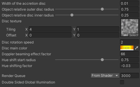
3 Raymarching a black hole
Why is this section called raymarching instead of raytracing? The names are often used interchangeably, but usually the difference is that in raymarching we’ll be evaluating the ray at distinct steps, instead of only evaluating it at intersections/surfaces.
We only need a few things in order to change our raytracing shader to a raymarching shader, without changing the outcome yet. We need some variables to hold our current ray position and direction, a loop in which we move our ray forward and some properties to control this loop. Add two new properties to the shader, one for the amount of steps and one for the step size we’ll be using in the march.
Properties{
    ...
    _Steps ("Amount of steps", int) = 256
    _StepSize ("Step size", Range(0.001, 1)) = 0.1
}

...
vert(){}
...
int _Steps;
float _StepSize;
Now add the current ray position and direction variables to our ray information in the frag function. We add the outerSphereIntersection distance to our initial currentRayPos because we know there is nothing to evaluate before entering the outer sphere.
// Ray information
float transmittance = 0;
float3 samplePos = float3(maxFloat, 0, 0);
float3 currentRayPos = rayOrigin + rayDir * outerSphereIntersection.x;
float3 currentRayDir = rayDir;
Finally we’ll encapsulate our previous ray intersection code with a for loop and move our ray forward each loop. Now whenever we used to call rayOrigin or rayDir we will call currentRayPos and currentRayDir instead and check if we will intersect the disc within the next step. Replace the intersection code in the frag function with the highlighted code.
// Ray intersects with the outer sphere
if(outerSphereIntersection.x < maxFloat)
{
    for (int i = 0; i < _Steps; i++)
    {
        // Move ray forward
        currentRayPos += currentRayDir * _StepSize;

        // Check for disc intersection nearby
        float discDst = intersectDisc(currentRayPos, currentRayDir, p1, p2, discDir, discRadius, innerRadius);
        if(transmittance < 1 && discDst < _StepSize)
        {
            transmittance = 1;
            samplePos = currentRayPos + currentRayDir * discDst;
        }
    }
}3.1 Black hole
With what we already have adding the black hole in the middle is surprisingly easy. All we need to do is check if our ray enters a sphere and then use that as a mask for our background color. Of course we need to know how big this black hole is, so let’s start by adding a new property for it called _SSRadius.
Properties{
    ...
    _SSRadius ("Object relative Schwarzschild radius", Range(0,1)) = 0.2
}

...
vert(){}
...
float _SSRadius;For our mask we’ll add a new variable to the ray information and default it to 0, no black hole. Then in the raymarching we’ll check for nearby intersections with the black hole through our sphere intersection function. If the black hole is nearby we set the mask to 1. Note that we also break out of the loop, which is logical as light can’t escape the black hole and neither should our ray be able to continue. Add the highlighted code in the frag function and apply the mask to our backgroundCol.
// Ray information
float transmittance = 0;
float blackHoleMask = 0;
float3 samplePos = float3(maxFloat, 0, 0);
float3 currentRayPos = rayOrigin + rayDir * outerSphereIntersection.x;
float3 currentRayDir = rayDir;

// Ray intersects with the outer sphere
if(outerSphereIntersection.x < maxFloat)
{
    for (int i = 0; i < _Steps; i++)
    {
        // Move ray forward
        currentRayPos += currentRayDir * _StepSize;

        float blackHoleDistance = intersectSphere(currentRayPos, currentRayDir, IN.centre, _SSRadius * sphereRadius).x;
        if(blackHoleDistance <= _StepSize)
        {
            blackHoleMask = 1;
            break;
        }

...
float2 screenUV = IN.posCS.xy / _ScreenParams.xy;
float3 backgroundCol = SampleSceneColor(screenUV) * (1 - blackHoleMask);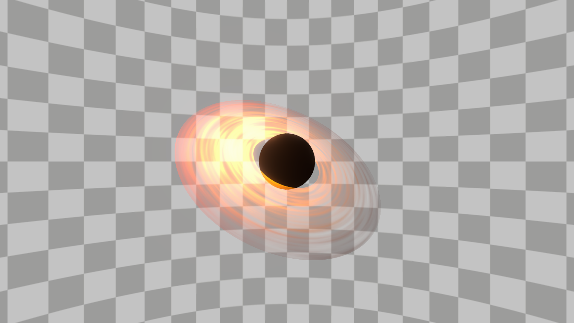
3.2 Gravity
Onto the interesting part, gravity. We’ll be using gravity solely to redirect our ray as we step through it, such that it can bend around the black hole and show what’s behind it. To do this we simplify the law of gravity to a gravitational constant, that we set, divided by the distance to the centre squared. Add the gravitational constant as a property.
Properties{
    ...
    _GConst ("Gravitational constant", float) = 0.15
}

...
vert(){}
...
float _GConst;
Now in our for loop we need to know the direction and distance towards the gravitational centre (the centre of our object) with regards to our current ray position. With this information we can also add another break statement, namely if our ray has left the outer sphere’s radius we no longer need to evaluate it. Note that we add the _StepSize to our check, this is to prevent situations where our initial ray might be ever so slightly outside the sphere’s radius. Finally, we calculate the gravitational force and redirect our ray by adding a scaled vector directed towards the gravitational centre. Add the highlighted code in the frag function.
// Ray intersects with the outer sphere
if(outerSphereIntersection.x < maxFloat)
{
for (int i = 0; i < _Steps; i++)
{
float3 dirToCentre = IN.centre-currentRayPos;
float dstToCentre = length(dirToCentre);
dirToCentre /= dstToCentre;
if(dstToCentre > sphereRadius + _StepSize)
{
break;
}
float force = _GConst/(dstToCentre*dstToCentre);
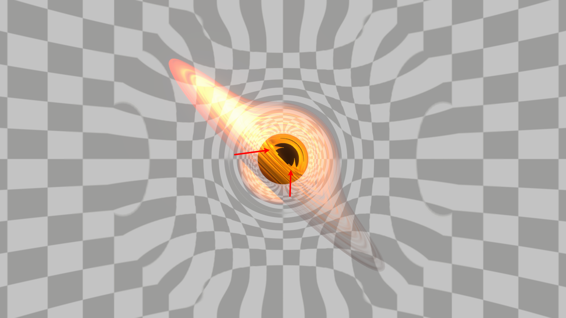
currentRayDir = normalize(currentRayDir + dirToCentre * force * _StepSize);If you look closely at the resulting image below, you’ll notice that there is also an inner ring just outside the black hole. This ring actually consists of rays that have orbited the black hole and collided with the disc from the other side, notice how the inner ring is brighter on the right instead of the left.
3.3 Space warping
We finally get to the part why we’ve been using this checkered skybox all this time, warping. In order to get some spatial warping we’ll be distorting the screenUV using the last ray position and use that to sample the opaque texture. We do this using a camera projection of a distorted ray direction, which we can use as UV coordinates. Ideally we would use currentRayDir, but those UVs could point to places that are outside our camera view. So instead we point to the last ray position where the loop terminated.
Replacing our screenUV with the distorted UVs would create very sharp transitions at the edge of our sphere gameObject and screen. In order to smooth these out a bit we’ll lerp between the normal screenUV and the distortedScreenUV, based on our distance to these edges. Add the highlighted code to the frag function and change the backgroundCol to use the distortedScreenUV.
float2 screenUV = IN.posCS.xy / _ScreenParams.xy;

// Ray direction projection
float3 distortedRayDir = normalize(currentRayPos - rayOrigin);
float4 rayCameraSpace = mul(unity_WorldToCamera, float4(distortedRayDir,0));
float4 rayUVProjection = mul(unity_CameraProjection, float4(rayCameraSpace));
float2 distortedScreenUV = rayUVProjection.xy + 1 * 0.5;

// Screen and object edge transitions
float edgeFadex = smoothstep(0, 0.25, 1 - abs(remap(screenUV.x, 0, 1, -1, 1)));
float edgeFadey = smoothstep(0, 0.25, 1 - abs(remap(screenUV.y, 0, 1, -1, 1)));
float t = saturate(remap(outerSphereIntersection.y, sphereRadius, 2 * sphereRadius, 0, 1)) * edgeFadex * edgeFadey;
distortedScreenUV = lerp(screenUV, distortedScreenUV, t);

float3 backgroundCol = SampleSceneColor(distortedScreenUV) * (1 - blackHoleMask);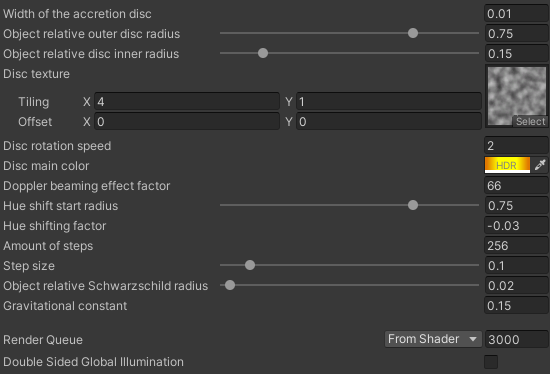
4 Conclusion
This is it, we’ve made a raymarching supermassive black hole shader! There are of course still lots of things that can be tweaked, such as the disc’s texture, or optimised, like the amount of steps taken. If you recreate this shader be sure to show me here, on twitter (@kelvinvanhoorn), or on reddit (u/Radagasd). Also, while not necessary I’ll very much appreciate it if you credit me when using this shader in your projects.
Thank you very much for reading and I hope you learned something new. If you want to support me financially you can do so using my ko-fi page.
Please let me know if you want me to create more tutorials and I would also greatly appreciate it if you could fill in this poll about the format of this tutorial.
4.1 Limitations
In this final section I’ll tell you briefly about some limitations and ideas that might solve them. The first being that we use the opaque texture to draw everything behind the black hole. This means that we won’t render any transparent objects (including other black holes) behind them. Unfortunately I do not have any easy solutions for this.
Secondly, we are culling the front and thus any opaque object that is within the sphere gameObject's radius is drawn on top of it. This could likely be fixed by setting the Cull to Off and instead doing some depth testing to see if the opaque object would be in front or behind the black hole.
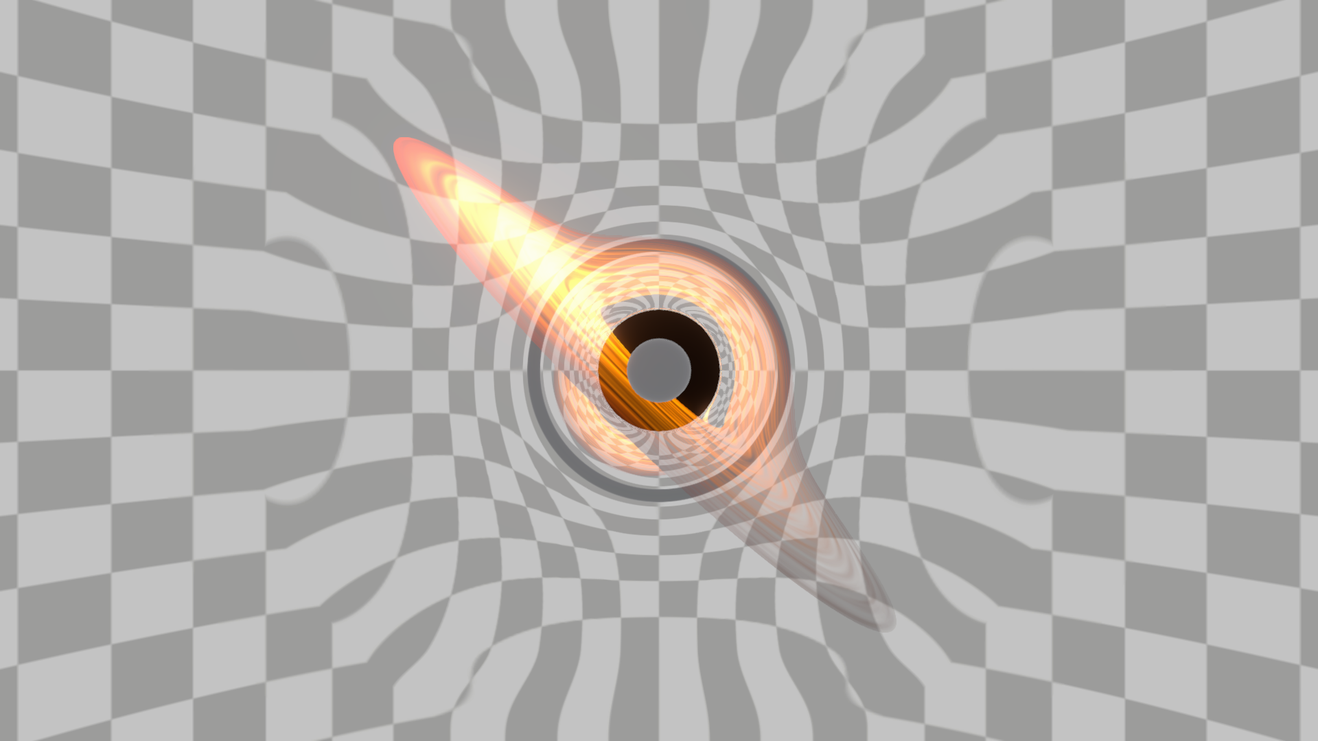
Thirdly, reducing the inner radius to be within the black hole creates stepping artifacts. Among other things the accuracy of our step size is too small here, where depending on the camera’s position a ray might or might not sample the accretion disc. While reducing the step size lessens this problem it increases the load of the shader. It’s best to keep your inner radius above the black hole’s range.
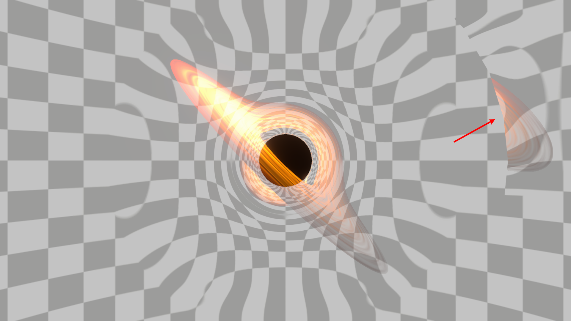
Lastly, we only take one sample position for our disc texture. This is only noticeable in the red boxed area of the picture below, the lower disc is abruptly cut as the other disc is in front of it. This could be fixed by checking and storing more sample positions and blending the texture samples in some way.

There are probably more limitations that I didn’t think of yet, but these are some of them. Thank you for reading this wall of text and be sure to share it with your friends or whoever else might be interested in it.